Inverter Circuit Mosfet
Normally for low and medium power applications power transistors are used.

Inverter circuit mosfet. Inverter simulation12v dc into 230 ac inverter mosfet circuit. The transformer is the most expensive part in an inverter circuit. The transformers limit can be calculated by multiplying voltage and current of secondary side of the step down transformer we are using in reverse so the inverter sees as step up transformer. 555 inverter circuit using mosfet in the circuit above is completely circuit diagram of this project.
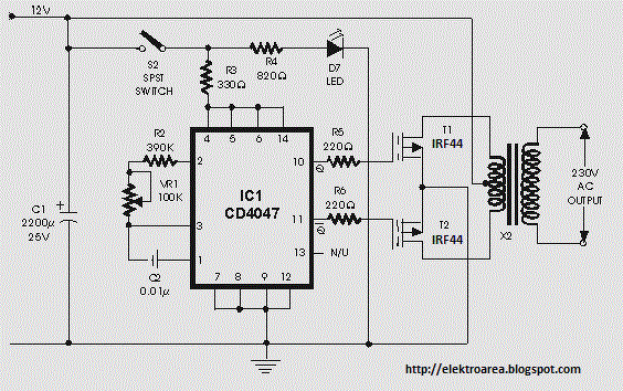
I use ic ne555 timer is a square wave frequency generator output of 50hz. You must use a battery and battery charger to implement this inverter circuit. Battery charging circuit is described in our previous post. The inverter circuit is built around ic cd4047 which is wired as astable multivibrator.
The operating frequency of astable multivibrator is set to 50hz. The proposed circuit is tested with irf540n but you can use any n channel mosfet. The irf540n can handle maximum current of 33a with its maximum temperature limit as per the data sheet. The irf540n can handle maximum current of 33a with its maximum temperature limit as per the data sheet.
Inverters are often needed at places where it is not possible to get ac supply from the mains. An inverter circuit is used to convert the dc power to ac power. Cd4047 inverter 1000w simple 12v inverter pdf inverter 12v 220v schematic drawing irfz44 in inverters irfz44 simpul invater diagram how to build dc to ac transistorised inverter 2000 watt inverter circuit diagram 1000 watt inverter circuit diagram pdf 12v to 220v 2000w inverter circuit diagram pdf dc to dc mosfet converter. 12v dc to 220v ac converter circuit using astable multivibrator inverter circuits can either use thyristors as switching devices or transistors.


+Circuit+diagram+using+CD4047+and+IRFZ44+power+MOSFET.png)


